 通用汽车的全新 L3B 汽油四缸发动机专为轻质卡车设计,这也是通用首次在全尺寸皮卡中使用的四缸发动机。
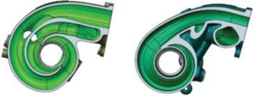
 通用汽车推进系统工程师表示,双蜗壳(左)和双涡流(右)涡轮增压器设计。其中,双蜗壳增压器的重量更轻,成本也有可能低于双涡流发动机。
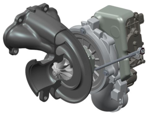
 博格华纳 B03 双蜗壳涡轮增压器的内蜗壳和外蜗壳呈同心圆排列(CAD 效果图)。
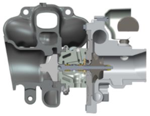
 博格华纳 B03 涡轮增压器的横截面。涡轮增压器的气流主要由A/R 比控制,即涡轮机壳体导管的横截面积除以导管圆心与涡轮机叶轮轴之间的距离后得到的值。
得益于博格华纳 (BorgWarner) 在涡轮增压技术方面的最新突破,通用汽车(GM)的全新 L3B 汽油四缸发动机获得了比V6 发动机更优越的功率和扭矩输出,可为全尺寸皮卡提供与柴油发动机媲美的燃油效率。
通用汽车(General Motors)专为卡车设计的全新 2.7L L3B 汽油四缸发动机配备丰富的先进功能,其功率输出比现行 4.3L LV3 六缸发动机高 9%、扭矩输出高 14%。现阶段,这款 L3B四缸涡轮增压发动机主要搭载 Hydra-Matic 8 速变速器 8L90,它也是 2019 款雪佛兰Silverados 皮卡(LT 级和RST 级)和 2019 款 GMC Sierra 皮卡的基础配置发动机。
简单来说,卡车的占空比范围更大,因此设计一款适合全尺寸皮卡的四缸增压发动机并非易事。在车辆挂高挡的稳定巡航状态下,涡轮增压发动机可以提供杰出的经济性,而一旦转速和增压升至一定水平即可提供充足的推力。但为卡车设计增压发动机的挑战在于不同操作模式之间的转换,也就是说当油门突然全开时,发动机如何才能立刻准备就绪开始运行。
Silverado皮卡首席工程师 Tom Sutter 解释说:“我们的目标是在节流阀升至 1500 rpm 后,让发动机在 2 秒内就具备输出 90% 峰值扭矩的能力,远超其他竞争对手。”
博格华纳和双蜗壳发动机
博格华纳(BorgWarner)的 B03 双涡壳涡轮增压器已经有数十年历史,但直到最近才应用至轻型车辆中。“我们从 2012 年开始尝试将这项技术从商用柴油发动机领域转移到轻型汽油发动机领域,”博格华纳全球工程和创新副总裁 Hermann Breitbach 博士指出,“双蜗壳涡轮增压器的优势在于节流阀响应,这种增压器的节流阀响应性能远超任何同类产品。”
简单来说,各类涡轮增压器的基本工作原理都一样,即从发动机排气口回收随废气一起排出的能量。具体来说,涡轮增压器利用这些热气推动涡轮叶轮旋转,进而驱动离心式压缩机为气体加压,最终即迫使这些高于大气压的高压气体流入进气歧管。一个多世纪以来,这项由瑞士工程师 Alfred Buchi 推出的重大创新已经帮助无数飞机、轮船、卡车和汽车发动机提高了输出功率和工作效率。
正如上文的介绍,为了能够使发动机排气口排出的热气顺利推动涡轮叶轮的旋转,所有涡轮增压器都必须让这些热气在抵达涡轮叶轮前形成旋转的涡流。通常来说,这个步骤是由一条弯曲的管道来实现的,也就是涡轮增压器的蜗壳管道或涡流管道。根据蜗壳或涡轮的不同设计,涡轮增压器对热气中的热量和动量的利用效率也有不同。
当发动机转速较高时,涡轮增压器将使用一根粗管道处理这些废气,而且几乎不会对气体流动施加任何限制。然而,当发动机转速较低时,涡轮需要些许推力才能开始旋转。为此,双蜗壳增压器在在涡轮机入口处设计了两根缠绕其上的管道,连接废气出口,保证每次的排气都能“尽全力”推动涡轮机叶轮转动。
专为四缸发动机工况量身定制
考虑到全新 L3B 发动机采用了 1-3-4-2 的点火顺序,最佳布置应为:将发动机的气缸 1 和气缸 4 连接至涡轮增压器的一根管道,并将气缸 3 和气缸 2 连接到另一根管道。这样做能够尽可能增加每股废气之间的间隔,并降低废气抵达叶轮前被中断的可能性。
接着,下一个需要考虑的问题是管道与涡轮机的连接。通常来说,“双涡流”涡轮机的设计更加常见,也就是说将两条管道并排放置。遗憾的是,在这种设计下,废气流出管道的位置可能出现短路,也就是说,当从两根管道排出的气流本应共同推动涡轮叶轮转动时,却可能由于相互碰撞和冲击而意外流回管道中。对于大中型发动机而言,这并不是什么大问题。但对于较小的四缸发动机而言,这种短路会增加涡轮延迟,也就是延缓涡轮增压器增压的速度。
对比之下,双蜗壳发动机的两根管道则呈同心圆排列,内部管道在即将抵达叶轮时,会先在涡轮机外壳之外绕半圈,而外部管道还会再多绕半圈,从而避免了任何短路或相互干扰的可能性。
博格华纳北美工程总监 Douglas Erber 表示,“这种双蜗壳分离设计可以增加高压气体脉冲之间的间隔,确保让更多能量抵达涡轮,总体可以减少涡轮延迟,并显著改善节流阀响应性能。”
当 L3B发动机转速在 1500 rpm 时,增压废气将以 40 毫秒的周期轮番冲击增压器叶轮的不同侧面,使其快速加速旋转。蜗壳管道出口与涡轮叶轮之间的间隙只有 1 毫米(0.039 英寸),而双涡流涡轮通常则有 5 毫米(0.197英寸)的间隙。
细心的观察者可能会注意到,在双蜗壳增压器中,外蜗壳的横截面积要比内蜗壳更大。这是由于涡轮增压器的气流主要由A/R 比控制,即涡轮机壳体导管的横截面积除以导管圆心与涡轮机叶轮轴之间的距离得到的比值。因此,为了使双蜗壳设计的两个蜗壳都具备相同的 A/R 和相似的流动特性,外蜗壳的面积必须更大。
当然了,在一些发动机设计中,双蜗壳增压器内外蜗壳的A/R 可能会特意略有不同。然而,经过工程师的验证,对于 L3B 发动机来说,相同的A/R 比更加适合。
多种配置
L3B发动机助理总工程师 Craig Marriott 解释道:“我们在早期研发中评估对比了多种不同的涡轮配置,最终确定双蜗壳增压器的架构最适合我们的卡车应用。这种涡轮增压器不仅可以显著优化发动机的瞬时响应性能,甚至还稍稍提高了发动机的峰值功率输出。”
在L3B 卡车发动机中,B03 涡轮增压器可以提供 22 psi(1.5 bar)的增压。
当被问及这项技术是否可能扩展到其他通用涡轮增压发动机时,Marriott 补充道,“目前,我还无法透露未来计划,但请保持期待!”
在重量、体积和成本方面,通用汽车的涡轮增压器工程师Alec Peeples 透露,双蜗壳设计“比双涡流设计略轻,因为双蜗壳增压器中的内蜗壳仅绕了一个半圈,此外同心圆的布局也稍微更紧凑一些,尽管确实从中心轴线向外延伸得更远。由于涡轮机壳体材料相对较重且成本较高,因此双蜗壳设计可能比双涡流设计更便宜。”
博格华纳 Erber 表示,这两种设计的成本非常相似。他补充说,事实上,推进系统工程师在选择增压器时,不仅可以考虑双蜗壳设计、双涡流设计、单蜗壳设计,而且还可以考虑一些可变叶轮设计,重点是了解每个产品都有自己独特的需求。
不过,无论具体选择哪种类型的涡轮增压器,毫无疑问,这项由瑞典工程师Alfred Buchi 在 1905 年创造的发明将继续协助更多发动机产品不断提高性能。
The first four-cylinder gasoline engine ever offered in a full-sized pickup truck brings V6-beating power and torque, with fuel efficiency that is expected to rival a diesel. And key to its performance is a new twist in turbocharging.
GM’s all-new 2.7-L L3B was designed for truck use, with a wealth of advanced features (see https://www.sae.org/news/2018/05/gm-2.7-l-i-4-revealed). The result is 9% more power and 14% more torque than GM’s incumbent LV3 4.3-L V6. Teamed with the 8L90 8-speed Hydra-Matic transmission, the L3B turbo four is the base engine for 2019 Chevy Silverados in LT and RST trim and also is offered for the 2019 GMC Sierra, which shares the Silverado’s all-new architecture.
Engineering a boosted I4 for fullsize pickups’ broad duty cycle was no mean feat. Such engines provide impressive economy during steady-state cruising in top gear and generate ample thrust under load once the revs and boost are up. The challenge is in the transition between those operating modes—when the engine must leap into action as the throttle is quickly moved from barely open to WOT.
“Our goal was to top every competitor by providing 90% of peak torque less than two seconds after the throttle is floored at 1500 rpm,” explained Silverado chief engineer Tom Sutter.
BorgWarner and dual-volute
Enter BorgWarner’s B03 dual-volute (DV) turbocharger—a design that’s existed for decades but is new to light-duty vehicle applications. “We began transferring this technology from commercial diesels to light-duty gasoline engines in 2012,” noted Dr. Hermann Breitbach, BW’s VP of global engineering and innovation. “The advantage a DV turbo offers is throttle response that’s superior to any alternative.”
All turbos recycle energy that exits the engine’s exhaust ports. The hot gas spins a turbine wheel which in turn drives a centrifugal compressor that forces intake air—above atmospheric pressure—through the intake manifold. Swiss engineer Alfred Buchi’s invention has boosted aircraft, ship, truck and automobile engine power and efficiency for more than a century.
In every turbocharger application, the linear stream of hot gas exiting the exhaust manifold must be twisted into a spiral to spin the turbine wheel. This is achieved by means of a curved duct inside the turbine housing called a scroll or volute. The configuration of these ducts determines how efficiently they exploit the exhaust stream’s heat and momentum.
A single large duct handles the exhaust flow with minimal restriction at high rpm. At low rpm, however, the turbine needs a nudge to start spinning. In the dual-volute design, that’s achieved by using two ducts wrapped around the turbine inlet, with exhaust port connections that encourage every burst of exhaust gas to strike the turbine wheel with maximum force.
Specifically tailored for 4-cylinder duty
Given the new L3B’s 1-3-4-2 firing order, connecting cylinders 1 and 4 to one of the turbocharger’s ducts and cylinders 3 and 2 to the other duct is the optimum arrangement. This maximizes the separation between bursts of exhaust gas and minimizes the flow disruption before the gasses reach the turbine wheel.
The next consideration is how the ducts meet the turbine. The more common configuration, typically called “twin scroll,” has the two ducts positioned side-by-side. Unfortunately, this allows short circuiting where the exhaust gas leaves the ducts: as the two streams mix just before they strike the turbine wheel, a small portion of the exhaust gas runs the wrong way back up a duct. That’s not an issue in medium to large engines, but it can increase turbo lag—a delayed arrival of boost pressure—in small four-cylinder engines.
A DV design locates one duct inside the other in a concentric arrangement. The inner channel wraps half way around the turbine housing before its exhaust gas impinges against the wheel. The outer volute carries on an additional 180 degrees to guard against short circuiting and any chance of unproductive flow interference.
BorgWarner’s North American engineering director, Douglas Erber, said, “DV segregation and the resulting greater spacing between exhaust pressure pulses assures that more energy reaches the turbine wheel. This diminishes lag and significantly improves throttle response.”
At 1500 rpm, each side of the L3B engine’s turbine wheel is struck by an exhaust pulse every 40 milliseconds, quickly accelerating its rotation. The gap between each volute’s exit and the turbine wheel is only 1 mm (.039 in.) compared to the 5-mm gap that’s common for a twin scroll turbo.
Close observers will note that the outer volute has a larger cross-sectional area than the inner volute. This is because a turbocharger’s flow is governed by its A/R ratio—the cross-sectional area of the turbine housing’s duct divided by the distance between the duct’s centroid and the turbine wheel’s axis; for both volutes of a dual-volute design to share a common A/R and similar flow characteristics, the area of the outer volute must be larger. While there are situations when slightly different A/R volutes are desirable, engineers determined they should be identical in the L3B application.
Multiple configurations tested
Craig Marriott, assistant chief engineer for the L3B engine explained: “While evaluating several turbo configurations during the alpha [early] phase of development, we determined that the DV architecture demonstrated the best performance for our truck application. In addition to its significant improvement in transient response, we found a small horsepower gain at the top end.”
The B03 is capable of generating 22-psi (1.5-bar) boost in the L3B truck engine application.
Asked if this technology is likely to extend to other GM turbo engines, he added, “I’m not at liberty to speak of future plans except to recommend staying tuned!”
Regarding weight, bulk and cost considerations, GM’s turbocharger engineer Alec Peeples revealed that the DV design “is slightly lighter than the twin-scroll alternative because one of the two volutes wraps only half way around the wheel. The concentric layout is also somewhat narrower, though it does extend further outboard from the center axis. Since the turbine housing material is relatively heavy and costly, the DV design is potentially less-expensive than twin scroll.”
According BW’s Erber, the costs are very similar for both designs. He added that propulsion-system engineers will be wise to consider not only DV, twin-scroll and single-scroll turbos but also variable-vane designs, as each product application has specific needs.
Whatever the case, Alfred Buchi’s 1905 invention is the engine power-enhancing technology gift that keeps on giving.
Author: Don Sherman
Source: SAE Automotive Engineering Magazine
等级
打分
- 2分
- 4分
- 6分
- 8分
- 10分
平均分
- 作者:Don Sherman
- 行业:汽车
- 主题:制造零部件动力与推进力质量、可靠性与耐久性车辆与性能
